GEOTECHNICAL ENGINEERING
HOUSTON
HomeGeophysicsElectrical resistivity / VES (Vertical Electrical Sounding)

Electrical Resistivity Surveys and Vertical Electrical Sounding in Houston

Evidence-based design. Reliable delivery.

LEARN MORE

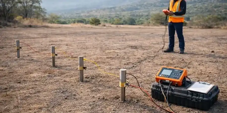
The subsurface conditions across Houston can vary dramatically within a single project site. Over in the Heights, you might hit stiff Beaumont Formation clays just a few feet down, while a site near the Ship Channel in Harrisburg sits atop layers of soft, compressible Holocene alluvium interbedded with sand and saltwater. This sharp contrast means that relying solely on a SPT drilling program or isolated test pits may not give you the full lateral picture of what lies beneath. Our team uses electrical resistivity imaging and vertical electrical sounding (VES) to bridge that gap, profiling changes in soil moisture, clay content, and salinity across the entire site before the first auger even turns. In a city built on bayous and reclaimed wetlands, understanding where the conductive clays pinch out against resistive sands is what keeps excavation plans safe and foundation recommendations realistic.

Resistivity contrasts in the Gulf Coast plain often reveal what borings miss: the exact boundary where a clean sand channel transitions into a conductive, high-plasticity clay.
Our service areas

Our approach and scope

Houston's humid subtropical climate and its relentless summer heat waves create a specific challenge for resistivity work: electrode contact resistance can spike when the expansive surface clays bake dry under 100-degree sun. We precondition the electrode array with saline solution when necessary, a trick learned from years of working the Gulf Coast's shrink-swell terrain. The real value of combining VES with a CPT test lies in calibrating resistivity profiles directly against cone tip resistance and sleeve friction, which lets us identify not just the geometry of a buried channel sand but also its relative density. For environmental assessments near the refineries along the Houston Ship Channel, resistivity is often the fastest way to map the lateral extent of a saline plume, and we frequently integrate these results with grain size analysis to confirm the connection between pore fluid conductivity and the actual soil texture. Whether it is characterizing the stiff Pleistocene clays under the Energy Corridor or delineating a paleochannel beneath the Katy Prairie, the method adapts to the wide-ranging depositional environments that define this metro area.
Electrical Resistivity Surveys and Vertical Electrical Sounding in Houston
Technical reference — Houston

Local ground factors

The Beaumont and Lissie formations that underlie much of Houston are notorious for containing perched brackish water zones and deeper saline aquifers, particularly in areas south of the Buffalo Bayou fault system and across the coastal plain toward Galveston Bay. When resistivity surveys misinterpret a drop in apparent resistivity as a simple clay layer rather than a saline sand, the consequences for deep excavation dewatering or foundation design can be severe. We have seen projects near Clear Lake where a VES profile indicated a continuous low-resistivity unit at 40 feet that turned out to be a confined saltwater sand, not the stiff clay the original geotechnical model assumed. Correlating resistivity data with liquefaction assessment parameters becomes critical in these settings, because saturated, loose sands with high pore-water conductivity behave very differently under seismic loading than the resistive, dense sands found further inland. The Houston area sits outside the highest seismic hazard zones, but the USGS still assigns a moderate risk to the region, and the presence of the active Long Point-Eureka Heights fault system means that site-specific stratigraphic models built on resistivity data must be interpreted with an eye toward both pore fluid chemistry and structural geology.

Need a geotechnical assessment?

Reply within 24h.

Email: [email protected]

Regulatory framework

ASTM D6431-18 Standard Guide for Using the Direct Current Resistivity Method for Subsurface Site Characterization, ASTM D2487-17 Standard Practice for Classification of Soils for Engineering Purposes (Unified Soil Classification System), IBC 2021 Chapter 18 Soils and Foundations

Reference parameters

ParameterTypical value
MethodVertical Electrical Sounding (VES) and 2D Electrical Resistivity Tomography (ERT)
Array configurationsSchlumberger, Wenner, and Dipole-Dipole
StandardASTM D6431-18 for subsurface imaging
Typical investigation depth3 to 100 meters below grade, depending on array spread
Key targetStratigraphic boundaries, saline water zones, clay-sand interfaces, and buried paleochannels
Data output2D resistivity cross-sections, VES layered models, and 3D fence diagrams for site-wide assessment
Complementary testsCone penetration testing (CPT), standard penetration testing (SPT), and groundwater conductivity sampling

Common questions

What is the typical depth range for a VES survey in the Houston area?

The investigation depth depends on the maximum electrode spread we can deploy at your site. Using a Schlumberger array with a current electrode separation of 300 meters, we can typically resolve resistivity layers down to about 60 to 80 meters below ground surface. In urban Houston, where space may be limited by existing structures or right-of-way constraints, we often use 2D ERT lines with tighter electrode spacing to achieve 15 to 30 meters of penetration, which covers the critical zone for shallow foundations and utilities.

How much does an electrical resistivity survey cost in Houston?

For a typical site investigation involving a single VES sounding or a short 2D resistivity line of approximately 100 to 200 linear feet, the cost generally ranges from US$670 to US$1,110. The final price depends on the total line length, the required electrode spacing, site accessibility, and whether we need to integrate the resistivity data with CPT or SPT calibration points. Larger projects with multiple parallel lines or 3D grid surveys are quoted on a case-by-case basis after reviewing the site plan.

Can resistivity testing detect abandoned pipelines or underground storage tanks?

Electrical resistivity methods respond strongly to metallic objects buried in the subsurface, so a well-planned survey can often identify the location of abandoned pipelines, USTs, or other conductive anomalies. However, the primary purpose of a geotechnical resistivity survey is to map natural soil and rock stratigraphy. For a dedicated utility and infrastructure detection project, we usually recommend combining resistivity with ground-penetrating radar or electromagnetic induction methods to increase the confidence of the target identification.

Location and service area

We serve projects in Houston and surrounding areas.

View larger map